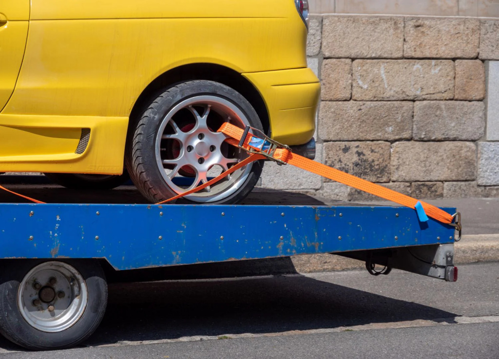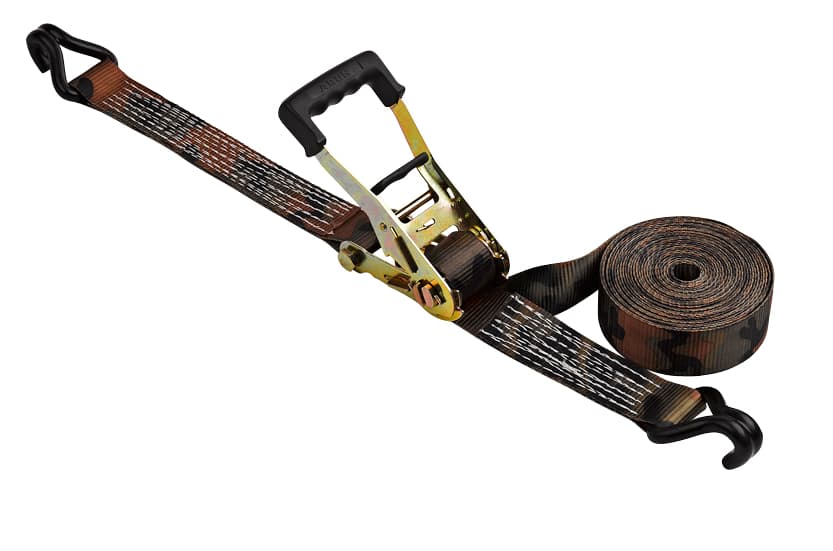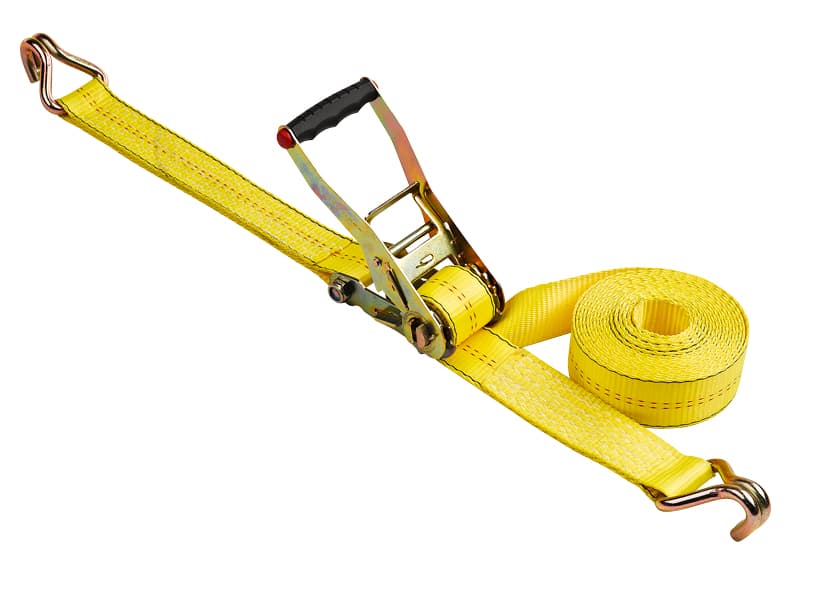
Cam‑buckle tie‑downs are widely deployed for light‑to‑medium cargo securement across pickup trucks, trailers, and flat‑bed transport. Although the threading workflow appears simple, field surveys from cargo‑handling practice show that improper installation is the leading cause of strap slippage and load shift during transit. Many consumer‑level guides only list step‑by‑step actions without explaining the underlying friction‑locking mechanics, hardware limitations, and real‑world failure modes. This document provides operation workflows, hardware mechanics, controlled release methods, failure‑mode analysis, and safety practice aligned with widely‑accepted cargo‑restraint industry conventions.
Key Takeaways
- Insert free‑end webbing through the bottom slot, route over the serrated cam face, and exit via the top slot; hold the release lever open during insertion to avoid damaging webbing and cam teeth.
- Webbing must remain fully flat and untwisted within the buckle interface. Even partial twist reduces engaged contact area and degrades rated holding capacity.
- Always reference the hardware‑marked Working Load Limit (WLL). Cam buckles rely on spring‑assisted friction locking and shall not be used for overhead lifting, fall protection, or personnel‑related load suspension.
- Inspect webbing, stitching, and metal hardware before every use; retire components that show cuts, abrasion, metal deformation, or UV‑induced material degradation.
- Perform two‑hand controlled release; never release a strap under heavy live tension to prevent dangerous strap recoil and premature hardware wear.
Cam Buckle Technical Background
Construction & Locking Principle of Metal Cam Buckles
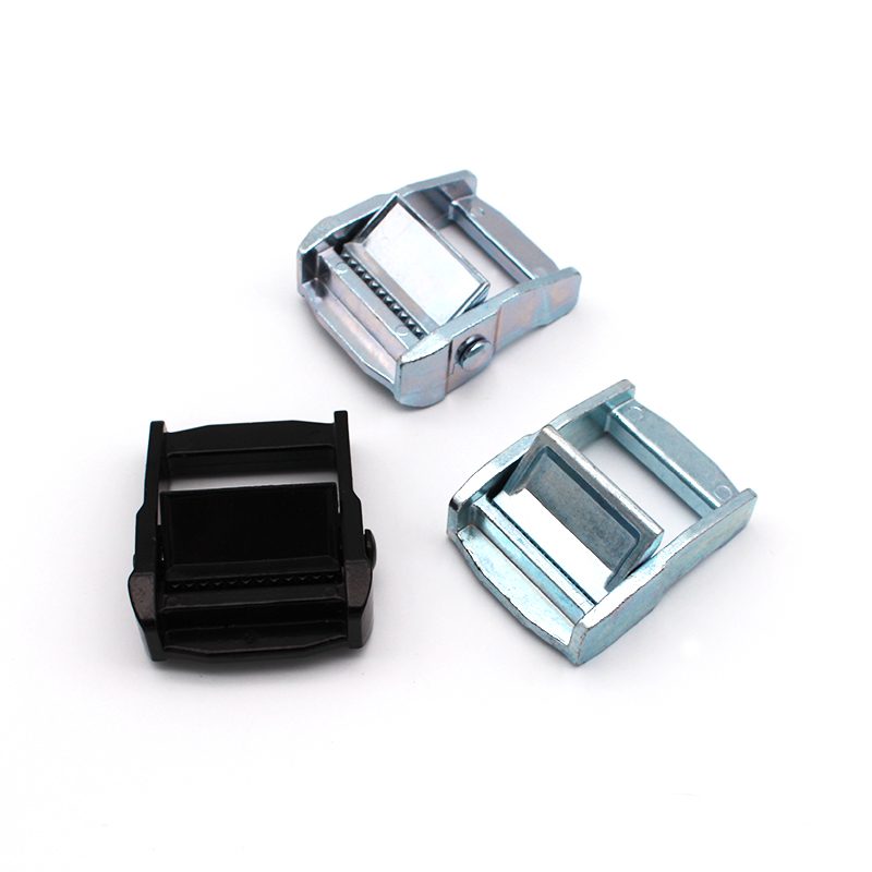
Typical stamped‑metal cam‑buckle hardware contains these core parts: metal frame housing, spring‑loaded pivoting cam with serrated gripping teeth, bottom inlet slot, top outlet slot, and manual release lever.
The locking mechanism functions purely by mechanical friction and clamping force. When tension pulls on the free webbing tail, load reaction pushes the cam pivot downwards. Serrated teeth press into polyester webbing and squeeze the fabric firmly against the inner frame surface. The built‑in coil spring maintains baseline clamping pressure even after manual pulling stops, helping resist slip under vibration, cornering shock, and road impacts.
Depressing the release lever lifts the cam, disengages serrations from webbing, and removes clamping force so the strap can be adjusted or removed.
Reference context: This friction‑based locking principle is described within general cargo‑control guidance for synthetic‑webbing tie‑down assemblies. Note that cam‑buckle assemblies produce far lower pre‑tension compared to ratchet‑style tie‑downs, a well‑documented performance difference in cargo‑securement resources.
How Webbing Twist Creates Hidden Failure Risk
Many end‑users underestimate the impact of minor webbing twists. If twisted webbing passes through the buckle, only a fraction of the strap width makes contact with cam serrations. Two measurable risks follow:
- Stress concentration concentrates load onto a narrow webbing strip, raising risk of tearing under dynamic shock loads.
- Reduced tooth‑to‑fabric contact lowers friction; cyclic vibration may produce “creep”, allowing the strap to gradually slip over time.
Recommended field practice: Unspool the full strap length onto a flat surface before threading. Run hands along the entire webbing to eliminate twists, folds and kinks. Only when full‑width contact is achieved can the buckle perform at its labelled working‑load capacity. Flat webbing also reduces localized abrasion and extends service life.
Step‑by‑Step: How to Loop and Thread a Metal Cam Buckle
First identify the two strap ends:
- Fixed end: Permanently attached to hooks or anchor loops.
- Free end: Loose webbing tail threaded through the buckle for tension adjustment.
Important: Keep the release lever depressed to open the cam gap when feeding webbing. Forcing webbing past closed cam teeth will nick fabric and wear serrated edges prematurely.
- Feed free‑end webbing into the bottom inlet slotPress the release lever down to hold the cam open. Feed the webbing tail upward through the bottom slot so it emerges on the cam side of the metal frame.
- Route over cam and exit through top slotGuide webbing across the full serrated face of the cam, then thread out via the top slot. Maintain flat orientation; avoid folding or twisting. Confirm the full width of webbing lies flush against cam teeth.
- Tighten and lockRelease the operating lever. Pull the free tail firmly until cargo is held snug. The spring‑loaded cam drops automatically into locked position. Additional tension created by cargo movement during transport will further increase clamping force.
Special Scenario: Girth‑Hitch Anchor Loop
When an anchor point cannot accept direct strap‑end threading, use a girth‑hitch connection:
Pass the webbing loop under the anchor fixture. Feed the entire cam‑buckle assembly through this loop, then draw tight around the anchor point. Ensure the loop itself remains flat and twist‑free before applying tension. This creates a robust indirect anchor connection.
Documented Common Field Mistakes
These error patterns appear repeatedly in real‑world cargo‑securement practice:
- Feeding webbing without depressing the release lever, damaging webbing and cam serrations.
- Only checking webbing near the buckle while leaving twists elsewhere along the strap run.
- Running webbing across sharp metal edges without edge protection sleeves, generating cut notches that become failure initiation points.
- Selecting cam‑buckle straps for heavy loads that require ratchet‑style tie‑down hardware, due to misunderstanding achievable pre‑tension limits.
- Continued use of webbing degraded by UV light, fraying, or deep cuts. Faded textile material indicates polymer chain degradation and reduced ultimate breaking strength.
Safe Release Workflow for Cam Buckles
Improper release accelerates pivot‑point wear, distorts internal springs, and creates hazardous strap snap‑back.
- Where possible, reduce cargo‑induced tension before actuating the buckle. Do not fully release a strap still under high working‑load tension.
- Use two‑hand technique: One hand fully depresses and holds down the release lever to keep the cam lifted open. The second hand steadily pulls webbing out of the buckle slots.
- Release tension gradually. Sudden recoil can injure operators and damage adjacent equipment.
Keeping the cam open during webbing withdrawal prevents serrated teeth from gouging the strap surface during removal. Consistent gentle handling extends overall assembly service life.
Load‑Rating, Safety Standards & Inspection Regimes
Reference note: Working Load Limit (WLL) and safety‑factor conventions for cargo tie‑downs are widely referenced within North American and European cargo‑restraint guidance for non‑lifting tie‑down applications. Safety factor represents the ratio between ultimate breaking strength and allowable working load. Cam‑buckle tie‑downs are for cargo restraint only; they are not designed for overhead lifting or fall‑arrest purposes.
| Cargo Category | Typical Minimum Safety Factor | Common Working Load Range |
|---|---|---|
| General transit cargo | 2:1 | 1 000 – 5 000 lbs |
| Hazardous‑material transport | 3:1 | 5 000 – 10 000 lbs |
| High‑value / fragile cargo | ≥3:1 | Application‑specific |
Practical operational note: Specify straps against maximum foreseeable dynamic load rather than static average weight. Braking, cornering and road shock can multiply effective load forces on tie‑down hardware.
Mandatory Pre‑Use and Storage‑Period Inspection
Inspect every strap before each deployment:
- Webbing: cuts, fraying, abrasive wear, UV discoloration, brittle or softened fabric areas.
- Metal hardware: cam‑tooth condition, spring function, frame cracks or bending deformation.
- Stitching: pulled threads, broken seams at hook and anchor connections.
Storage‑time inspection schedule:
- Cool, dry indoor storage: full inspection every 6 months.
- High‑humidity, outdoor, extreme‑temperature storage: inspect every 3 months.
Discard any assembly showing damage. Damaged webbing or deformed metal buckles cannot be reliably repaired in‑field.
Closing Summary
Proper cam‑buckle threading: feed through bottom slot, pass over serrated cam surface, exit top slot. Full‑width, untwisted webbing contact is required to achieve published performance. Spring‑powered friction locking delivers reliable medium‑duty cargo restraint, yet hardware has clear design limits.
Operators must follow labelled WLL values, perform systematic inspections, avoid lifting applications, and execute controlled two‑hand release. Real‑world performance depends far more on correct installation and inspection than on hardware alone., exit the top slot, maintain flat untwisted webbing, then apply tension. The spring‑driven friction‑lock mechanism delivers reliable holding performance only when the full strap width engages the cam teeth.
Operators must respect WLL ratings, complete routine hardware and fabric inspections, avoid overhead lifting applications, and follow controlled two‑hand release techniques. Cam buckles deliver dependable medium‑duty cargo restraint, but performance depends entirely on proper threading, good pre‑use inspection and respect for hardware design limits.